Dr. Chris Rogish has a very successful family practice in Ohio, and he discusses why he decided to get a new digital panoramic x-ray. He also shares his experience with the Panoura 18S panoramic x-ray from ImageWorks.
In our experience, we have seen doctors take a wide variety of approaches to how they charge for the dental cone beam scans. Clearly there are a number of variables that would affect the pricing strategy including specialty and the intent of the scan. However, we will provide some thoughts from a few General Dentists, which are the more common dental professional that we work with.
One particular general dentist has set up their pricing strategy based on the FOV of the scan. Because the X-era offers a number of different fields of view, here is his approach:
Small field of view scan (4” diam scan): $120-$150
Medium field of view scan (8” diam scan): $200-$250
Large field of view scan (16” diam scan): $300-$350
If the patient opts to move forward with an implant treatment, that scan may be offered complimentary.
We have also seen scenarios where the dental professional may identify some pathology via a traditional 2D modality like an intraoral periapical or a panoramic x-ray. The dental professional may deem that the cone beam scan will not only provide critical additional information to improve confidence in the diagnosis, but it will also allow for a more detailed treatment plan.
In these situations, we have heard from some doctors who may decide not to charge the patient for the scan. They may waive this fee in these scenarios because they feel the cone beam scan will help them:
Communicate the diagnosis and treatment options in a more compelling way, thereby increasing the probability and speed of case acceptance
Save time in performing a procedure because the scan gives them so much more information to plan the procedure, and virtually eliminates “surprises”
In these unique cases, they may decide that these alternative benefits are immediate enough to preclude the need to charge the patient.
While every dental professional must decide what right for their practice, these are a few approaches that may be helpful. We would love to hear your thoughts!
At ImageWorks, we have helped many thousands of dental professionals optimize their digital imaging, and here is a common scenario:
The office has a digital intraoral system, and they need to add a sensor. They don’t want to overpay for a name brand sensor. However, they need to make sure the staff will be able to efficiently capture great intraoral images.
Therefore, they are looking for a sensor that not only works well, but also works well with their existing software.
To find the right sensor for this office, there are obvious aspects to consider like image quality of the sensor and support from the provider. However, there are two often overlooked aspects that can help an office save money on a sensor system without sacrificing quality or workflow efficiency.
Does the sensor slow the hygienist down during the capture sequence?
Many 3rd party sensors may be able to capture an image into your imaging software. However, during multi-image capture sequences (e.g. a bitewing study, FMX, etc) many of these sensors will require the hygienist to click in the software after capturing each image.
For hygienists, capturing intraoral images is already a complex process with many moving parts. Further difficulty arises with a patient that may be in some level of discomfort during the process. As a result, using a sensor system that requires the hygienist to also click on the PC in between every exposure may make both the staff and the patients very grumpy.
Does the sensor offer image optimization filters?
This is an important and sometimes overlooked capability for a few reasons. First, it’s worth noting that filters play an important role in the resulting image quality of every sensor. A sensor that has poorly applied filters will result in a poor image no matter how great the sensor is.
Second, many times the imaging software cannot (or will not) apply any filters to the image captured with a 3rd party sensor. As a result, the sensor must have its own filter capability to assure the resulting images will reflect the true quality of the sensor.
If you want to maximize your ROI with a sensor that is going to give you fantastic images, give us a call to see how we can help you.
Dr. Leo Galletto has been practicing dentistry for many years. He is an orthodontist that currently operates a number of offices in the Philadelphia area. He recently implemented a few pan ceph systems from ImageWorks in his offices. He shares his experience making the migration from film to digital, and the support he received from ImageWorks along the way.
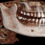
Dr. Ed Warr is a really sharp general dentist in Ashland, OR. He has been using the X-era Cone Beam system from ImageWorks for close to two years. He shares a number of cases including a tooth fracture and a sinus evaluation where the image resolution of the X-era brought really critical information to light.
Dr. Edison Louie is a fantastic general dentist in Anaheim, CA, who has been practicing for well over 40 years. He installed an X-era Cone Beam system from ImageWorks about two years ago in his office, and we recently caught up with him so that he could share specific examples and case studies of how it has transformed his practice. We created a video of everything he showed us, and it’s amazing what he’s been doing!