In order to assure that Dental Cone Beam CTs are being used safely and effectively, almost all states require that the Dental Cone Beam equipment have a mechanism to confirm it is operating properly year after year in a dental office. This process can be confusing for a dental office because what’s required can vary between states, and the process can vary between manufacturers. In fact, some first-time cone beam users may not be aware there is a requirement.
Typically, this procedure is generally referred to as “QA”, which is short for Quality Assurance. For dental cone beam systems, this QA procedure across all manufacturers utilizes a tool referred to as the Quality Assurance, or QA, phantom.
To shed some light on this topic, we wanted to provide answers to some commonly asked questions about keeping your system compliant.
What is the QA phantom used for?
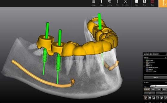
The QA phantom is a component that is scanned by the dental cone beam CT, and the resulting scan of this phantom is evaluated in specific ways. If this evaluation passes a specific set of metrics, it serves as an indication that the cone beam CT is operating correctly. This process is typically a core piece of the quality assurance, or QA, process.
Where do I get it?
Most commonly, this will come from the manufacturer of the cone beam. However, there are independent companies that also provide dental cone beam CT phantoms.
Are they all the same?
No. While there are many similarities, each one typically has its own unique characteristics. It’s also important to know that each phantom provider has a unique process to use it, including what measurements to take.
What does it look like?
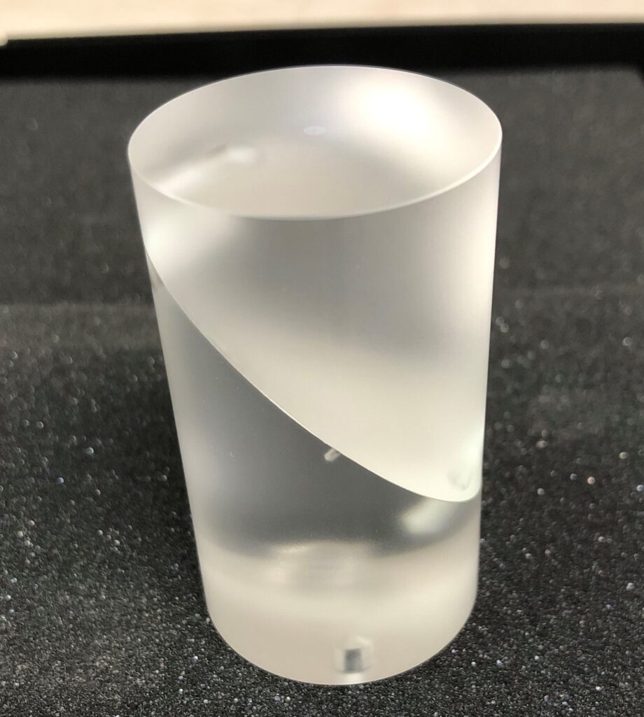
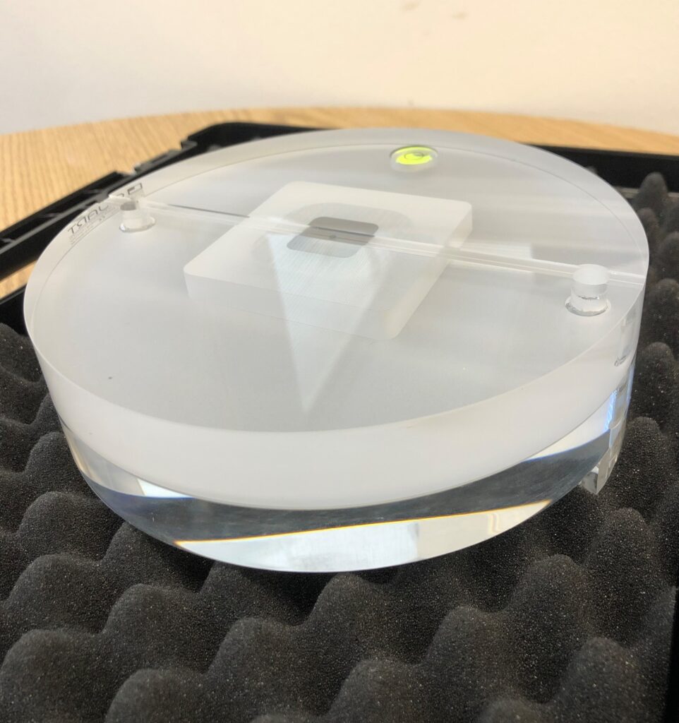
While they are all different, they are typically cylindrical and made of a clear resin material. They will typically also have different layers and some specific items embedded in them. Here are a few examples:
I have a technician who services my office and my unit. Does my staff really need to know how to use this phantom?
It depends. Some states require the office to perform the QA tests periodically (using the phantom), and sometimes an inspector will want to see evidence that this has been happening. As an aside, performing this check is typically not that hard, and can be done fairly quickly.
How do I use the phantom?
This procedure on how to use it will come from the manufacturer, and the procedure is most commonly detailed in the User’s Manual. While phantoms vary, there are some similarities. Typically, it involves placing the phantom in the field of the view of the unit and taking a scan. Then the QA process involves performing a number of simple measurements on the resulting image using the software.
These measurements will be looking at spatial accuracy, noise levels, contrast resolution, slice thickness and other parameters.
I have a Dental Cone Beam and I don’t know where my QA phantom is.
You are not alone. This is unfortunately an all too common occurrence as sometimes these items get lost in the office over time. It’s highly recommended to designate a place to store this (and other maintenance accessories for the cone beam) and then inform the entire staff of this location.
Learn more about Imaging Solutions from ImageWorks
Subscribe to Receive More Great Articles